
IOlog Modules Remote Test
Users and developers can test IOlog data acquisition modules using a testing system; it can be accessed at “iolog.sielcosistemi.com” using Modbus TCP protocol on port 502.
This provides a way to directly communicate with remote IOlog modules using your own supervisory software or PLC, or by downloading Winlog Evo and running the Circuit Demo project.
The system is designed to provide feedback to the user and verify that the commands sent are executed. SS3130 digital outputs are connected to SS3148 digital inputs; SS3024 analog outputs are connected to SS3017-I analog inputs, as shown in the reference image. Furthermore, four thermocouple sensors are connected to module SS3016 to measure the temperature of the environment.
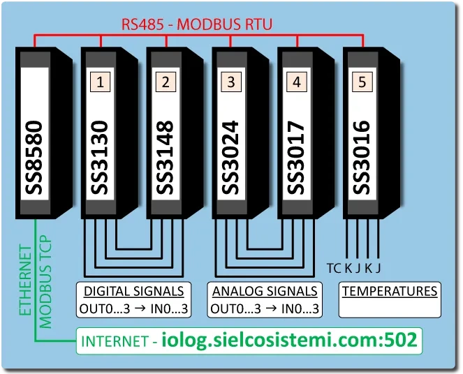
Module and variable address mapping
The table below provides description, device Modbus address and datasheet and user guide download links for each module in the test system.
| Model | Description | Modbus address | Datasheet | User Guide |
|---|---|---|---|---|
| SS8580 | Converter from Modbus TCP Ethernet to Modbus RTU RS485 | - | ||
| SS3130 | Digital module with 4 digital inputs and 4 relay outputs | 1 | ||
| SS3148 | Digital module with 12 digital inputs | 2 | ||
| SS3024 | Analog module with 4 voltage or current outputs | 3 | ||
| SS3017-I | Analog module with 8 current inputs | 4 | ||
| SS3016 | Analog module with 4 thermocouple inputs | 5 |
 EN
EN IT
ITFor each device, the user guide provides its “Modbus map”, a table that assigns each shared variable to the corresponding Modbus address. There are two kinds of variable:
register: 2 bytes (16 bit word) used to represent analog inputs, analog outputs, or numeric variables;
coil: a single bit used to represent digital inputs (contacts), digital outputs (relais), or logical states (alarms, flags, etc.).
A register can also be used to group several coils into a single value. For example, the digital inputs of a device can also be read together as a single register (16-bit word), where each bit corresponds to a coil.